HUMMEL-Connectors may not be connected or disconnected under voltage. In order to guarantee the IP protection class and the necessary contact overlapping, the cable and coupling connectors must be inserted and locked as far as it will go.
The air gap is the shortest distance in air between two conductive parts.
The clearances in HUMMEL products are dimensioned for altitudes up to and including 2000 m above sea level (NN). For air distances over 2000 m, altitude correction factors apply, please contact our technical specialist.
The creepage distance is the shortest distance along the surface of an insulating material between two conductive parts.
Plug devices are plug-in connectors which, when used as intended, live or under load, may be plugged in or disconnected. Sockets are also known as CBC (connector with breaking capacity). A classic example from the household is the SCHUKO plug.
Connectors that may not be plugged in or disconnected under load or live when used as intended are also called COC (connector without breaking capacity).
HUMMEL connectors are usually classified as COC, so they must not be connected or disconnected when live!
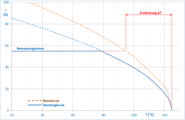
The derating curve (current-carrying capacity curve) describes the maximum permissible power loss of an electrical or electronic component as a function of its ambient temperature below its upper limit temperature (see above). The configuration and wiring of the component is important for this (number and cross-section of the energized conductors in connectors).
Example: In the curve, the component should only be operated up to 40 A at an ambient temperature of 100°C without exceeding the upper limit temperature.
The degree of pollution is a numerical value that indicates the expected pollution of the microenvironment and is a parameter when dimensioning the air and creepage distances in electrical equipment. It describes the possible contamination of an open, unmated connector in a certain environment. The EN 60664-1 standard distinguishes between four categories:
If connectors are used with a higher degree of pollution, the voltage values must be reduced. Please contact our technical specialists.
UL94 is a standard used by the American test laboratory Underwriters Laboratories, in which the burning properties and fire safety of plastics are examined. The UL 94 HB (Horizontal Burning) test tests the burning of a horizontal piece of plastic and the more demanding test UL 94 V (Vertical Burning) tests the burning of a vertical piece. The exact explanations about the systems used, the conditions and the test system can be found in the written UL 95 standard.
Example: UL identification for flammability UL 94 V (test of vertical combustion)
| Flammability classes UL 94 | |||
| V-0 | V-1 | V-2 | |
| Afterburning time after flame treatment (s) | ≤ 10 | ≤ 30 | ≤ 30 |
| Sum of all afterburning times (s) (10 flames) | ≤ 50 | ≤ 250 | ≤ 250 |
| Afterburning and afterglow of the samples after the second flame (s) | ≤ 30 | ≤ 60 | ≤ 60 |
| Burning dripping (ignition of the absorbent cotton) | No | No | Yes |
| Complete burning of the samples | No | No | No |
Functional earth (FE) is an electrical conductor, to ensure the functions and thus the regular operation of systems and devices.
Functional earth conductor: Grounding conductor for the purpose of functional grounding.
Functional ground: Earthing of a point or several points in a network, a system or an operating device for purposes other than electrical safety.
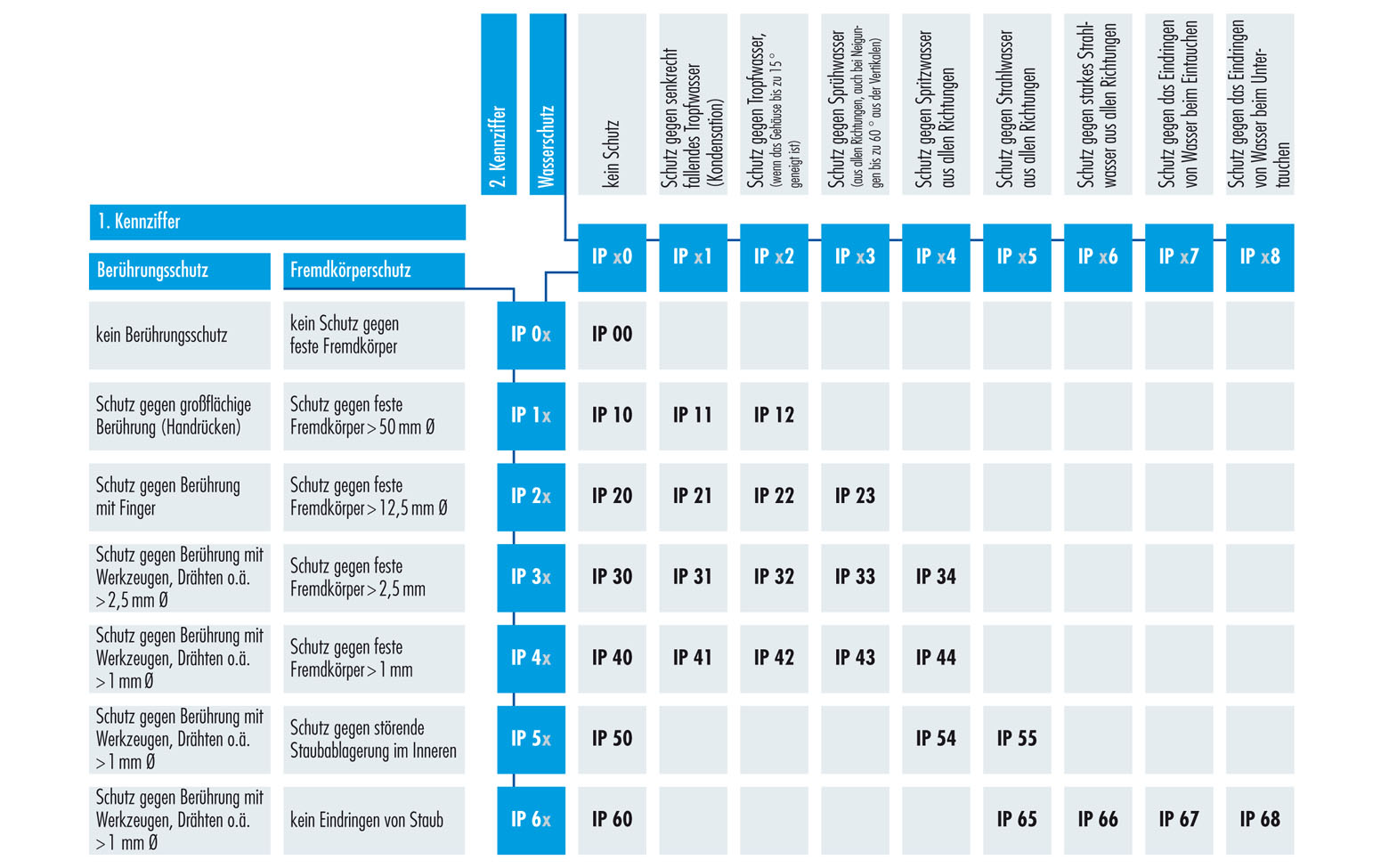
With regard to their suitability for various environmental conditions, electrical equipment is designed in accordance with EN 60529 with suitable degrees of protection expressed by IP codes. The abbreviation IP stands for Ingress Protection (protection against ingress). The letters IP are followed by 2 digits describing protection against foreign bodies/contact (st digit) and protection against water (2nd digit).
To ensure the IP protection class and the necessary contact overlap, the cable connector and the coupling connector must be plugged in and locked up to the stop.
Upper and lower temperatures that do not damage the materials are referred to as limit temperatures. In between lies the operating temperature range (e.g. -40 ... +125°C)
The lower limit temperature is the lowest permissible temperature at which a connector or plug device may still be operated
The upper limit temperature is the highest permissible temperature at which a plug connector or plug device may still be operated. It is equal to the sum of self-heating (contact heating and heating of the cable) and the maximum ambient temperature.
An insertion and removal process of connectors is referred to as a mating cycle. The number of mating cycles is an important parameter for plugs and connectors. It defines the service life of a connector, which it can complete without any loss of transmission quality. The quality of the contact surface in particular has an influence on the number of mating cycles. The use of high-quality and durable contact coatings reduce surface abrasion during the mating process.
In general, contact overlap or mating security in connectors refers to the possible overlap area of pin and socket. The larger this area, the more reliable the connection due to the higher possible tolerance compensation.
At HUMMEL, in order to guarantee the IP protection class and the necessary contact coverage, cable and coupling connectors must be plugged in and locked as far as they will go.
The overvoltage category is a (Roman) numerical value that defines a condition with regard to transient overvoltages for equipment that is fed directly from the low-voltage network:
Protective conductor (PE) is an electr. conductor for the purpose of safety, for example to protect against electric shock. It is also known as the earth conductor, or “earth” for short. Task in electr. Systems is the protection of living beings in the event of a failure.
PE conductor: Protective conductor for the purpose of protective earthing
Protective earthing: earthing of one or more points in the network, in a system or in equipment for the purpose of electrical safety.
The rated current is the current value, preferably at an ambient temperature of 40°C, which the connector can carry continuously (without interruption) and which flows simultaneously through all contacts connected to the largest fixed conductor without exceeding the upper limit temperature.
When considering the current carrying capacity of the connector, the current carrying capacity of the lines and cables used must be taken into account. This is primarily dependent on the permissible limit temperatures (see below), but also on the cross-section of the conductors and their bundling and installation situation. To this end, the manufacturer's instructions or standards such as: DIN VDE 0298-4 or IEC 60364-5-52 must be observed. Here are some extracts from DIN VDE 0298-4:
Tables according to installation type:
Laying type | A1 | A2 | B1 | B2 | C | |||||
| Installation in thermally insulated walls | Laying in electrical installation pipes | Laying on a wall | ||||||||
| Number of loaded cores | 2 | 3 | 2 | 3 | 2 | 3 | 2 | 3 | 2 | 3 |
| Nominal cross-section in mm2 | Load capacity in A | |||||||||
| 1,5 | 15,5 | 13,5 | 15,5 | 13 | 17,5 | 15,5 | 16,5 | 15 | 19,5 | 17,5 |
| 2,5 | 19,5 | 18 | 18,5 | 17,5 | 24 | 21 | 23 | 20 | 27 | 24 |
| 4 | 26 | 24 | 25 | 23 | 32 | 28 | 30 | 27 | 36 | 32 |
| 4 | - | - | - | - | - | - | - | - | - | 33,02 |
| 6 | 34 | 31 | 32 | 29 | 41 | 36 | 38 | 34 | 46 | 41 |
| 10 | 46 | 42 | 43 | 39 | 57 | 50 | 52 | 46 | 63 | 57 |
| 10 | - | - | - | - | - | - | - | 47,17 | - | 59,43 |
| 16 | 61 | 56 | 57 | 52 | 76 | 68 | 69 | 62 | 85 | 76 |
| 25 | 80 | 73 | 75 | 68 | 101 | 89 | 90 | 80 | 112 | 96 |
| 35 | 99 | 89 | 92 | 83 | 125 | 110 | 111 | 99 | 138 | 119 |
| 50 | 119 | 108 | 110 | 99 | 151 | 134 | 133 | 118 | 168 | 144 |
| 70 | 151 | 136 | 139 | 125 | 192 | 171 | 168 | 149 | 213 | 184 |
| 95 | 182 | 164 | 167 | 150 | 232 | 207 | 201 | 179 | 258 | 223 |
| 120 | 210 | 188 | 192 | 172 | 269 | 239 | 232 | 206 | 299 | 259 |
| 150 | 240 | 216 | 219 | 196 | 300 | 262 | 258 | 225 | 344 | 299 |
| 185 | 273 | 245 | 248 | 223 | 341 | 296 | 294 | 255 | 392 | 341 |
| Laying type | D | E | F | G | |||||
| Laying in earth | Laying in the air | ||||||||
| Number of loaded cores | 2 | 3 | 2 | 3 | 2 | 3 | 2 | ||
| Nominal cross-section in mm2 | Load capacity in A | ||||||||
| 1,5 | 22 | 18 | 22 | 18,5 | - | - | - | - | - |
| 2,5 | 29 | 24 | 30 | 25 | - | - | - | - | - |
| 4 | 37 | 30 | 40 | 34 | - | - | - | - | - |
| 6 | 46 | 38 | 51 | 43 | - | - | - | - | - |
| 10 | 60 | 50 | 70 | 60 | - | - | - | - | - |
| 16 | 78 | 64 | 94 | 80 | - | - | - | - | - |
| 25 | 99 | 82 | 119 | 101 | 131 | 114 | 110 | 146 | 130 |
| 35 | 119 | 98 | 148 | 126 | 162 | 143 | 137 | 181 | 162 |
| 50 | 140 | 116 | 180 | 153 | 196 | 174 | 167 | 219 | 197 |
| 70 | 173 | 143 | 232 | 196 | 251 | 225 | 216 | 281 | 254 |
| 95 | 204 | 169 | 282 | 238 | 304 | 275 | 264 | 341 | 311 |
| 120 | 231 | 192 | 328 | 276 | 352 | 321 | 308 | 396 | 362 |
| 150 | 261 | 217 | 379 | 319 | 406 | 372 | 356 | 456 | 419 |
| 185 | 292 | 243 | 434 | 364 | 463 | 427 | 409 | 521 | 480 |
| 240 | 336 | 280 | 514 | 430 | 546 | 507 | 485 | 615 | 569 |
| 300 | 379 | 316 | 593 | 497 | 629 | 587 | 561 | 709 | 659 |
Conversion factors for different ambient temperatures:
| Permissible operating temperature | 40°C | 60°C | 70°C | 80°C | 85°C | 90°C |
| Ambient temperature in °C | Conversion factors | |||||
| 10 | 1,73 | 1,29 | 1,22 | 1,18 | 1,17 | 1,15 |
| 15 | 1,58 | 1,22 | 1,17 | 1,14 | 1,13 | 1,12 |
| 20 | 1,41 | 1,15 | 1,12 | 1,10 | 1,09 | 1,08 |
| 25 | 1,22 | 1,08 | 1,06 | 1,05 | 1,04 | 1,04 |
| 30 | 1,00 | 1,00 | 1,00 | 1,00 | 1,00 | 1,00 |
| 35 | 0,71 | 0,91 | 0,94 | 0,95 | 0,95 | 0,96 |
| 40 | - | 0,82 | 0,87 | 0,89 | 0,90 | 0,91 |
| 45 | - | 0,71 | 0,79 | 0,84 | 0,85 | 0,87 |
| 50 | - | 0,58 | 0,71 | 0,77 | - | 0,82 |
| 55 | - | 0,41 | 0,61 | 0,71 | - | 0,76 |
| 60 | - | - | 0,50 | 0,63 | - | 0,71 |
| 65 | - | - | 0,35 | 0,55 | - | 0,65 |
| 70 | - | - | - | 0,45 | - | 0,58 |
| 75 | - | - | - | 0,32 | - | 0,50 |
| 80 | - | - | - | - | - | 0,41 |
| 85 | - | - | - | - | - | 0,29 |
The rated impulse voltage is the value of a withstand impulse voltage that is specified by the manufacturer for a piece of equipment or for a part of it and which indicates the specified withstand capability of its associated insulation against transient overvoltages.
The level of the value is a measure of the minimum required air gap in the equipment.
| Voltage conductor to neutral conductor, derived from the nominal AC or nominal DC voltage up to and including | Rated impulse voltage | |||
| Overvoltage category | ||||
| I | II | III | IV | |
| V | V | V | V | V |
| 50 | 330 | 500 | 800 | 1500 |
| 100 | 500 | 800 | 1500 | 2500 |
| 150 | 800 | 1500 | 2500 | 4000 |
| 300 | 1500 | 2500 | 4000 | 6000 |
| 600 | 2500 | 4000 | 6000 | 8000 |
| 1000 | 4000 | 6000 | 8000 | 12000 |
The rated voltage is the specified value of the voltage to which the operating and performance characteristics are related. A connector can have more than one value of the rated voltage for the different voltage systems.
HUMMEL connectors can be used for DC (V=) and AC voltage (V~). For these cases, the rated voltage of the effective value of the maximum rated voltage line to neutral (UL-N). In 3-phase three-phase systems (V3~), the rated voltage is specified as phase voltage / conductor to conductor (UL-L).
In earthed networks (TN, TT, TN-C, TN-CS, ...) the voltage conductor to earth (UL-PE) is √3 less than the phase voltage (UL-L). In ungrounded networks, the conductor to earth voltage (UL-PE) is calculated to be the same as the conductor to conductor voltage (UL-L), i.e. not reduced by √3 because the star point (N) is not connected to earth (PE) is! This is important for dimensioning the clearances.
The test voltage is the voltage that a connector has to withstand under certain specifications without a voltage surge or voltage breakdown occurring over or through the insulation and corresponds at least to the withstand voltage in EN 61984.
The value of the test voltage is higher than the rated voltage and is used to verify the insulation capacity of the connector.
For operating voltages greater than 50 volts, the plug-in connectors listed in this catalog must have conductive housing parts in accordance with the safety regulations of DIN VDE 0100-410; IEC 60364-4-41 can be used. These safety regulations stipulate that the corresponding plug connectors must not be plugged in or disconnected while live. Otherwise no protection against electric shock is guaranteed.
